|
THD
Testing
Before
we proceed with power testing, substitute the dummy load
with a 200 watts, 8 ohms resistor. With the probes of the
THD analyzer connected across the load, spot frequencies
of 200Hz, 1KHz, 10KHz and 20KHz are used to test the amplifier's
THD at 1Watt, 60Watts and it's rated output of 125Watts.
You should be able to record similar readings as in Fig
5. It is recommended that the power heatsink and dummy load
be suitably cooled to avoid overheating. For 4 ohms testing,
replace load with a 400 watts resistor.
Fig
5 - THD + N


Note that as you gradually increase the output to maximum
level, the output waveform should not exhibit any signs
of distortion until clip.
Testing
the amplifier at Clip
In
Fig 6,7 and 8, the c200 is driven to 1% THD into 8 ohms
to determine the waveform at clip. Note the symmetrical
clipping at the three spot frequencies. With a 4 ohms resistive
load, similar results were observed.
The
Power Supply Unit (PSU)
The
PSU (Fig 9) is a conventional, unregulated supply. Input
fuse F1 is for safety. Mains switch SW1, has its contacts
straddled by a 4700pF X2 capacitor to suppress "popping"
during switch-on. T1 is the power transformer with a secondary
output of 40-0-40Vac. BR1 is the bridge rectifier and C2,C3
are the filter capacitors for DC smoothing. |
 Fig
6 - 1KHz Sine / 8 ohms
Fig
6 - 1KHz Sine / 8 ohms
@
1 % THD |

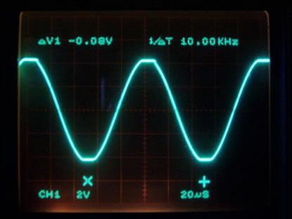
Fig 7 - 10KHz Sine / 8 ohms
@ 1 % THD

Fig 8 - 20KHz Sine / 8ohms
@
1% THD
|

Fig 9 - Power Supply Unit
|
For
monoblock, C2,C3 = 10,000uF x2/63V minimum.
Transformer secondary should be rated for 250VA.
For stereo, C2,C3 = 22,000uF x2/63V minimum.
Transformer should be upgraded to 500VA.
Supply rails (Vs) are +-53Vdc.
1
| 2 | 3
| 4 | 5 | 6
| 7 | 8
Next - Listening Test |